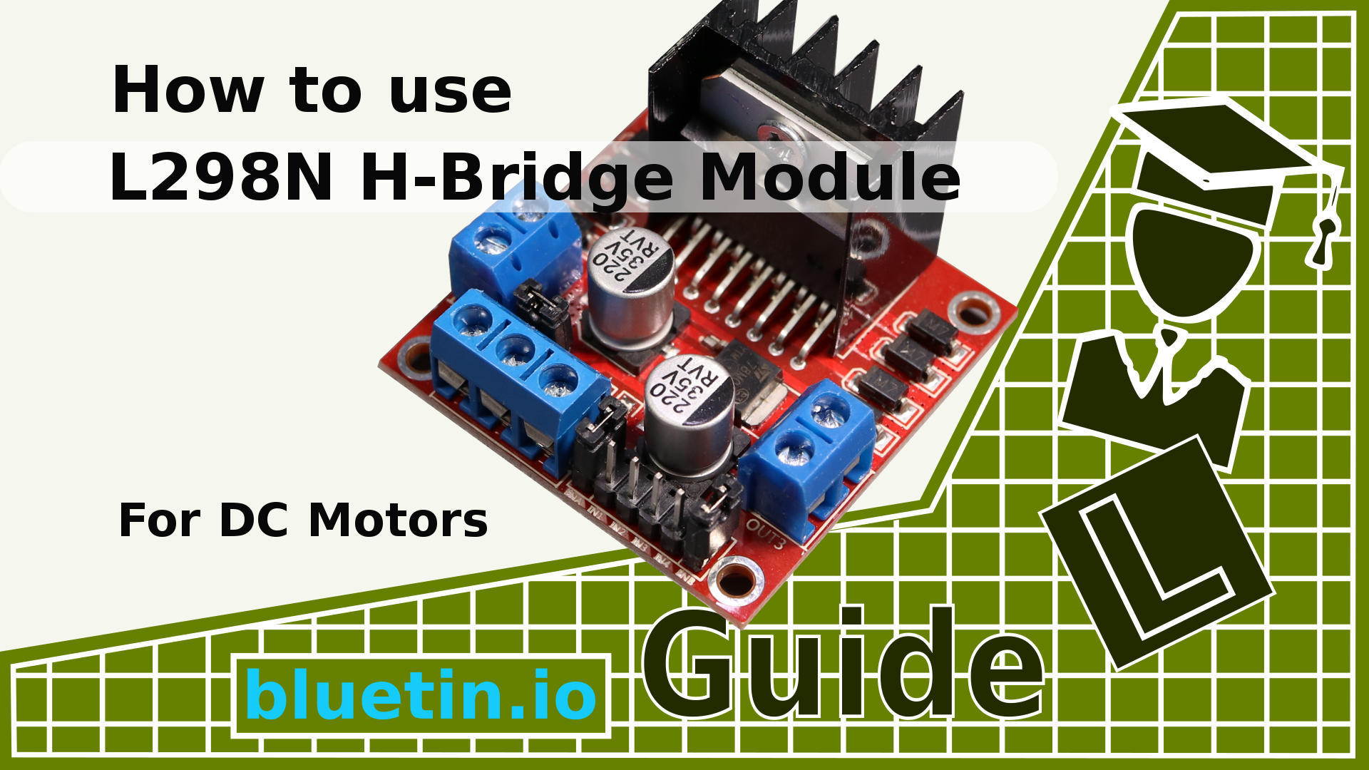

HOW TO USE THE L298N MOTOR DRIVER WITH ARDUINO CODE
The code is given below for above circuit.

The following image shows a simple circuit diagram, where a PWM output from Arduino is given to a MOSFET and the 12V DC Motor is connected through the MOSFET. The PWM Signal from any source like Arduino in this example, can be given to the gate of a MOSFET and depend on the duty cycle of the PWM Signal, the speed of the DC Motor will vary.

The duty cycle is usually expressed as a percentage, and the following figure shows several PWM signals from a 12V supply with different duty cycles of 0%, 25%, 50%, 75% and 100%, respectively. The working cycle of a PWM signal is nothing more than the ratio of the time the signal is activated or is HIGH to the total duration of the signal, that is, the time signal. Now, the average voltage applied to the DC motor depends on what is known as the work cycle of the PWM signal. The pulse width modulation or PWM signal generated by this technique allows us to control the average voltage delivered to the DC motor. If you want to control the rotational speed of a simple DC motor, there is a technique called PWM DC motor control. It is very easy to use: connect the two motor cables to the two terminals of a battery and that's it! Your motor starts spinning. Here we have different ways how to control a DC Motor and also this is quite popular for many reasons which are Arduino DC Motor control using L298N.Ī DC motor is the simplest motor that beginners and hobbyists know. In this Arduino project having main components are Arduino kit, DC motor L298N Motor Drive IC.


 0 kommentar(er)
